
As we wait for the USB Tester OLED backpack PCBs, I have started to develop the software that will run on it. If you missed it, here is a 3D model of the PCB: http://www.mobilewill.us/2012/12/3d-model-of-usb-tester-oled-adapter.html. Below is a picture of the display working on a breadboard. I am using an Xbee on a Sparkfun explorer as a load for testing. I even tested it with a Raspberry Pi while it is booting. Pretty neat, I am really excited to get this completed.
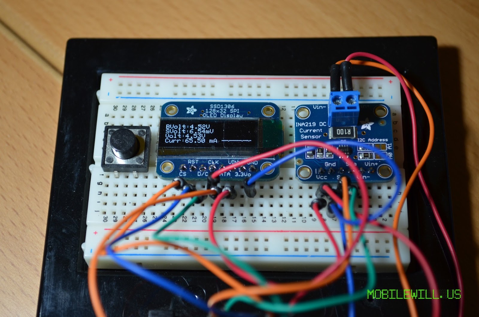 |
| USB Tester OLED Display |
On the breadboard you will see the Adafruit 128×32 SPI OLED display, INA219B DC High side current sensor (I2C), and a Arduino Leonardo. Currently the OLED display is using the default library that is bit banged SPI bit I will be updating it to use hardware SPI as that is how the PCB is laid out. Thanks to Nick Gammon for his work on making the library use hardware SPI. You can find his work here: http://arduino.cc/forum/index.php/topic,108542.
The PCBs are currently at the fab house, they should be in this week. I’ll post an update once they are in and when I have a prototype assembled. In that update there will be one surprise feature that I haven’t mentioned yet. Until then feel free to post any comments or suggestions for the final design. For example, I am toying with the idea of adding one or more buttons in case we want to add a menu system later on.