
Today on 12/12/12, we launched our first product! Check out the product description below. If you would like to purchase one you can do so here: https://www.tindie.com/shops/FriedCircuits/usb-tester/
We have launched a new name, FriedCircuits, which will be used for any products that we sell. I am working on a site for product information and documentation (will be shared when completed).
USB Tester v1
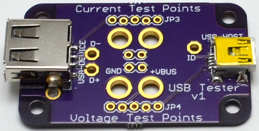 |
| USB Tester v1 Front |
 |
| USB Tester v1 Front with Jumper |
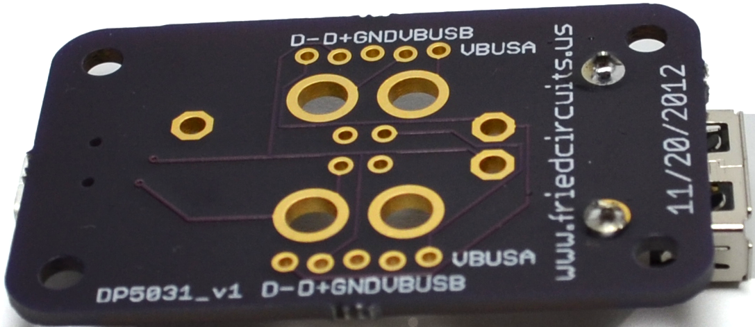 |
| USB Tester v1 Rear |
USB has become the core of many projects. In my experience I’ve found it to be troublesome to test USB voltage levels and current usage using a breadboard. They usually consist of holding wires attached to the DMM’s test leads, making it difficult to get solid readings. The USB Tester will make it much easier to monitor any USB project’s power source.
As part of the USB spec, you are limited to 500ma, so you want to monitor how close you are. Most people use USB hubs, both powered and unpowered, and with many devices connected, you can end up with less than 5V which can cause havoc on you projects. The USB Tester will make it a snap to monitor voltage levels and current usage without having to re-wire your breadboard. Just connect to your oscilloscope or DMM test leads, and you’re good to go! The USB Tester has both banana clip sized drills and standard 0.1” headers. When you are not testing current you can add a jumper for normal operation. The USB D+/D- pins are also broken out so you can monitor those on an oscilloscope, or for USB sniffing.
The USB Tester PCB size uses Dangerous prototypes Sick of Beige standard DP5031 so that a case can be used or at least a half of one as a base. The current batch is made in the U.S. using OSHPark’s PCB service.
Here is a list of features:
• Monitor voltage levels
• Monitor current usage
• Monitor data lines via an oscilloscope
• Banana clip testing points
• Jumper connection to bridge current connection when not testing/normal operation
• Dangerous Prototype’s Sick of Beige standard PCB size
• Headers for future expansion via backpacks
• Uses SparkFun’s 0.1″ locking header footprint
Included:
• Assembled PCB with both USB A and mini headers
• 14 unsoldered 0.1” pin headers
• 1 jumper
Note: a USB mini cable is not included
This product listing is to get a feel of interest of the USB Tester. If it does well, I will develop the backpacks, starting with an OLED display and any other ideas that conspire. Some of the ideas I currently have, is the ability to do data logging, either via local storage or a desktop application over a second USB connection.
Comment below with your thoughts or suggestions.
Comments 17
Hi. Just reblogged at recantha.co.uk/blog – looks like a great little board 🙂
Very nice board, but the store seems to have problems: It says "Only 1 left in stock" but if you try to add 1 to cart it says "The selected options are currently not in stock"….
Thanks, looking into it now.
I set it to zero and then 1 again. Try it and let me know.
Hey guys – thats actually the error message when another customer has the product in their cart and is still browsing/checking out. We definitely need a better message than that. I'm sorry about that! -Emile, founder of Tindie
If you look at how the USB standard is designed you will see that, because of voltage drop in connectors and cables, there are devices that accept only one cable. If you try to use more, or the device here, they will fail because of the voltage drop. When you add an extra cable and an extra pair of connectors and the multimeter wire resistance and the ampermeter resistance some devices will not work.
I've seen this problem on a few webcams and hard discs: even with a 15cm extension they will not start. True, your device will be suitable for some measurements, but not all.
The correct way to build this would be to have an external power supply that allows for current measurement but stabilizes the voltage at the pins of the host connector, to guarantee the voltage is within specs there.
Thanks for the feedback. When I develop the backpack for the display it will be using a separate power source. I was thinking another USB port, so that you can monitor without affecting what you are measuring.
I do have a USB HDD that has this problem. I have to use the supper short USB cable that came with it.
Part of the idea was to check if you are low because of a USB hub or your computer isn't putting out 5V. If I where to stabilize the voltage then it wouldn't be a good measurement when your device is ready to use without the USB Tester.
I have a USB hub that even when powered has low voltage and was causing problems on a project till i realized it.
What do you think would be a good way to go about it?
I can tell you that copying data from a SD card isn't affected by the USB Tester. Getting same speeds even connected with a unpowered USB hub.
I built something similar a while ago, I wrote about it here : http://www.youritronics.com/usb-a-to-micro-usb-bridge/
A reader quickly reminded me that USB traces are impedance controlled differential pairs and you gotta route them as 90 Ohm differential line.
Considering the short distance and the hobby nature of the project, it works, but as Bogdan said this kind of approach violates some USB standards.
Thanks, I did some reading up on that and it looks like I should be okay. I setup my ground plain on the same layer as the data lines and used 10mils trace width.
Looks like I could improve it by creating a ground plain on the bottom as well.
Correction: Ground plane.
This should be interesting to test charger in addition with a variable current drain.
I think adding data logging abilities will be really helpful to see data over time and different stages of a project.
It seems a bit inspired by my project published on october 2012
http://dangerousprototypes.com/forum/viewtopic.php?f=19&t=4613
Benjamin
I little bit, I had started mine and realized I used the same PCB size. But its the best size for it.
Do you have any problems with voltage drop? I haven't yet.