The first version of the USB Tester OLED backpack is now a working prototype! This version has all the features that I have posted about previously except for one unannounced feature that will be in the next PCB version which is due next week.
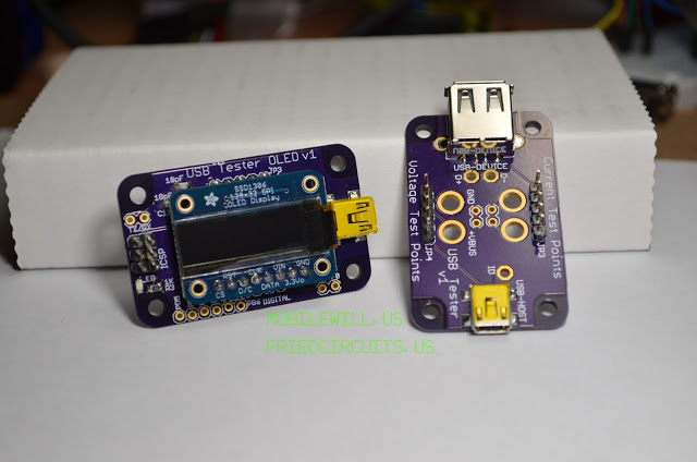 |
| USB Tester and OLED Backpack |
The OLED backpack adds a display to the USB Tester so that you don’t have to connect your multimeter. This makes it a snap to check voltage and current on the bench or on the go. Using the desktop Java application you can graph the data, save it to a text file and set a threshold current for the on board warning LED. Just connect your project to the USB A port like you would to your computer. Then connect both USB minis to your computer.
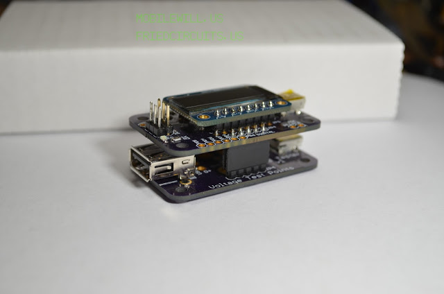 |
| USB Tester with OLED Backpack |
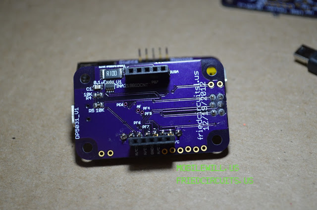 |
| Rear of USB Tester OLED Backpack |
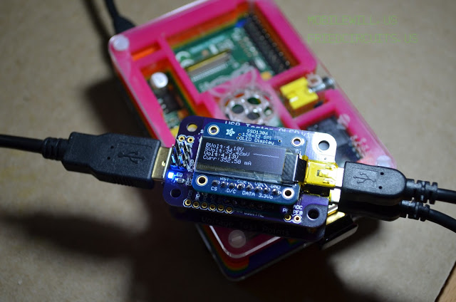 |
| USB Tester measuring Raspberry Pi, threshold set at 350mA |
The OLED backpack consists of a PCB the same size as the USB Tester but with female headers underneath and an Atmel Atmega32u4 microcontroller. The microcontroller reads the current and voltage via i2c from the INA219B from Texas Instruments. Thanks to Adafruit for exposing me to this IC, otherwise I wouldn’t of known of its existence. On the PCB below the microcontroller, there is a set of headers where Adafruit’s 128×32 SPI OLED display mates and displays the voltages, current, and mini graph. Any unused pins on the Atmega 32u4 have been broken out on the left and bottom sides of the PCB. There are a few pins I had to breakout with small via’s. With the included Arduino Leonardo bootloader you can easily add your own customizations. As an idea, you could program triggers based on voltage or current levels. If the current reaches a value, you can set a pin high that controls something else.
The available pins are:
Digital Header:
- TXRX
- PD5
- PD4
- PD7
- PB4
- PB7
- PE6
Analog Header:
- PF0
- PF1
Analog Via:
- AREF
- PF4
- PF5
- PF6
- PF7
The PCB will come assembled except for the female headers and the OLED display but both are included depending on which version you buy. I decided to offer it with different combinations so you can choose what works best for you.
- USB Tester OLED Backpack with OLED
- This is great for people who have a USB Tester and want the full backpack
- OLED Backpack
- OLED Display with 8 Position Male Header
- 2x 5 Position Female Headers
- USB Tester OLED backpack without OLED
- This is for people who either don’t want the OLED display or who have one already. You could also use this just for viewing the graphs on your computer and data logging.
- OLED Backpack
- 2x 5 Position Female Headers
- USB Tester Kit
- If you haven’t bought a USB Tester this will get you everything you need to get started
- USB Tester
- OLED Backpack
- OLED Display with 8 Position Male Header
- 2x 5 Position Female Headers
For your enjoyment, check out the additional photos below:
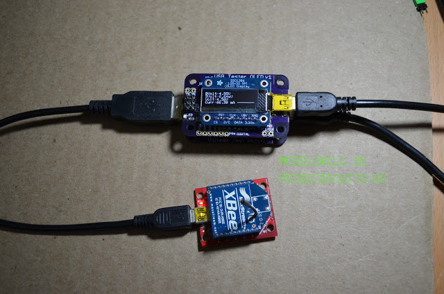 |
| USB Tester measuring Xbee Series 1 on Sparkfun explorer |
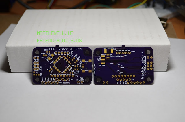 |
| USB Tester OLED Backpack PCB |
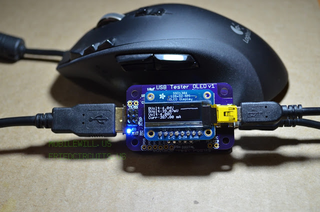 |
| USB Tester measuring my wireless mouse while charging, threshold set at 350mA |

Comments 6
Cool – received my "kit" the other day, soldered on the headers and now it's working. The good news is that my little "USB" solar panel does actually put out a reasonable 5V/500mA as advertised, but not I have a pretty display to tell me that rather than having to glob a multimeter onto it.
Have to start looking at the code to see what else I can make it do.
(I say "kit" because soldering headers onto a readymade, preprogrammed circuit board is not really kit assembly).
Thanks William.
what is the blue led for? sometimes it is on sometimes it is off even though the display continues to display data weather the led is off or on…
The blue LED is a current warn status. By default it turns on at 350mA. If you use the Java app you can change this set point.
thanx
nice share
Hello,
This is such a nice invention. There are many invention are going wrong because of correct use of scale of the uses thing. USB tester is very essential for us.