Living in an Apartment can be a challenge when it comes to home automation. Most projects require modifying or tapping into the building in one way or another. Our Apartment was remodeled before we moved in but they didn’t replace the aging thermostat. It is the old style with the lever on top that controls a glass tube of mercury. I knew I could replace the thermostat with some relays and a microcontroller or get a retail WiFi thermostat but I needed something that didn’t modify it in any away.

Looking through my inventory of parts I remembered I had a micro servo from the Adafruit Motor Shield kit. This servo with a microcontroller and a Wifly radio would be perfect. The idea is that the servo can set the temperature on the thermostat to give you remote control. The servo is connected to the lever on the thermostat with a paperclip. There was a few ways I could go about this. Either sync the microcontroller with the marked temp on the thermostat or use the lever as a switch. All the way to the right is “ON” and all the way to left will be “OFF”. My initial test was just moving the servo by 10 degress in either direction depending on which button or a command over WiFi.
My microcontroller of choice was the Romeo from DFRobot. I was given one after helping at the Maker Faire last year. It has everything I need for any project. Its really a great prototyping platform since it has a motor controller, breakouts for I2C, 5 buttons tied to a single ADC pin, and headers that have power, signal, and ground for servo and senors. You can check it out here: www.dfrobot.com (v1 with Atmega328p), they also have a newer one with the Atmega32u4 like the Leonardo here: www.dfrobot.com.
Parts:
- Romeo v1 (You can use v2 or any micro)
- Sparkfun Xbee Shield (needed a modification for the older shields)
- Wifly
- Micro Servo
- 9v Power Supply
- Paper Clip
- 3M Double Sided type
- LED for status (I use the one on pin 13)
- SHT1x Temp and Humidity Sensor (You could use any temp sensor)
This can be done with any microcontroller like a regular Arduino, you will just have to use a breadboard or a protoshield with some buttons. The Xbee shield does have prototyping space you could use. Later on, I do plan to make this more permanent with either a JeeNode or my own microcontroller design for home automation nodes and support for Lithium Ion batteries.
Assembly is pretty easy, the hardest part is probably the paperclip. As seen below you want to cut the paperclip just long enough to loop through the servo and wrap around the thermostat level. (This all depends on how yours is setup.) Cut a small piece of the 3M double sided tape and affix it to the bottom of the servo. Once you figure out your placement you can remove the adhesive cover and stick it. Give it a good squeeze so you get a good bond.
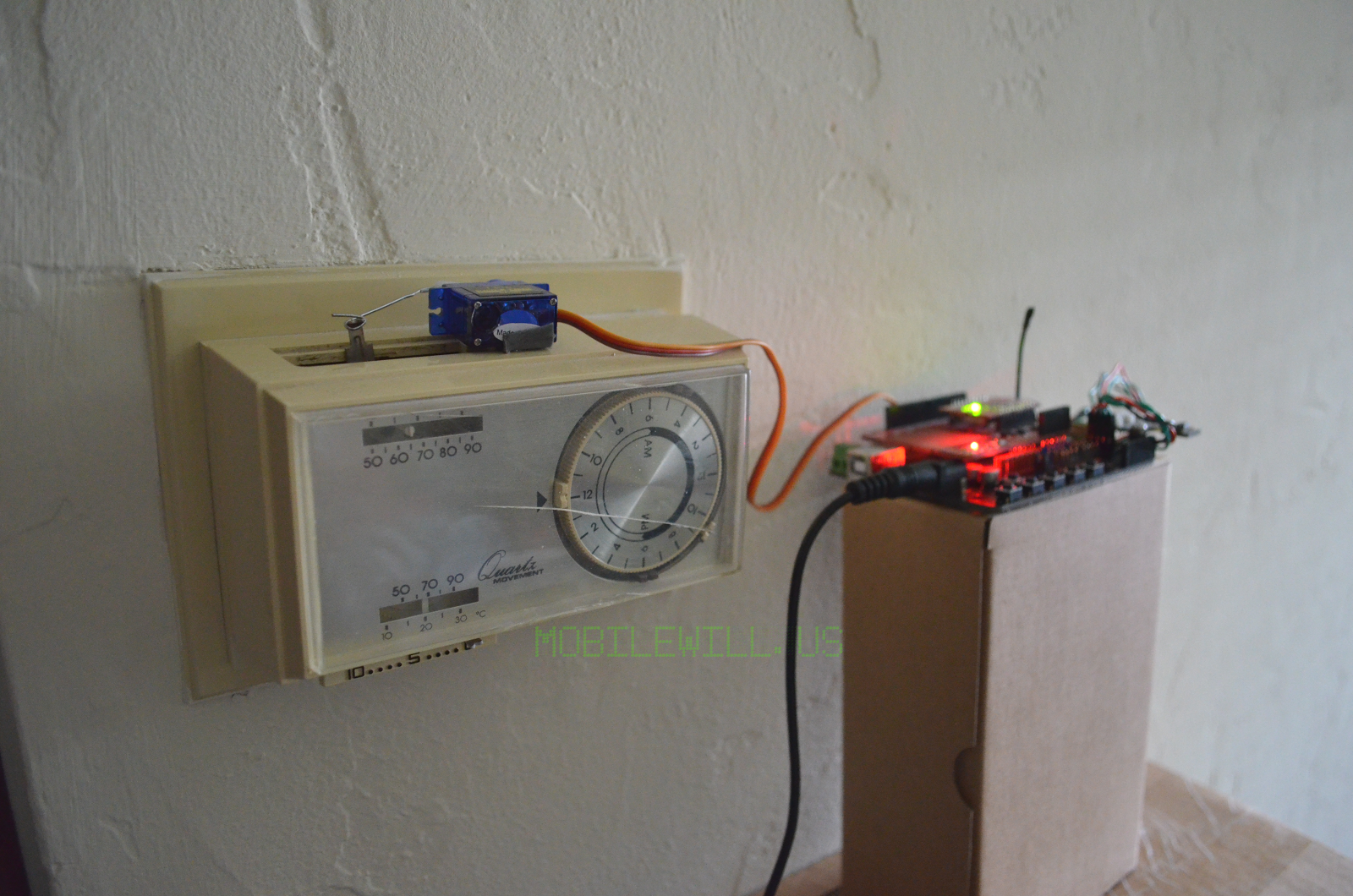
I connected the servo to the sensor header for pin 9 which has PWM. Add the Xbee shield and your choice of Xbee socket compatible radio. The original code I had used the buttons to move the servo 10 degrees and used the thermostat temp control. Once that was working reliable I added the SHT1x sensor. I had already used it on Sbot2 so it was a matter of swapping the sensor wire pin order and plugging it into the i2c header on the Romeo.
You can find the lastest version of the code on GitHub.
https://github.com/FriedCircuits/ServoThermostatControl
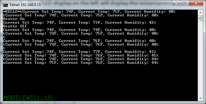
There are two ways to set the temp, either locally with the buttons or over a remote Telnet session which can be used from your mobile phone and a Telnet app. I plan on writing a web based GUI or maybe start building a mobile app for the whole home automation system. I would like to add voice control like I did with the smart outlet and the Raspberry Pi with the TV. http://www.mobilewill.us/2012/07/raspberry-pi-commandir-and-beyond.html
Here are the commands for the Telnet session:
- t – view set temp, air temp and humidity (Need to add heater status)
- o – forces off
- n – forces on
- u – raise set temp 1 degree
- d – lower set temp 1 degree
- Up – Raise temp 1 degree
- Down – Lower temp 1 degree
- Left – Force off
- Right – Force On
I hope this inspires home automation ideas for your home or apartment. If you have a project you would like to share you can email or comment below and I can post it up. Click on MrMobileWill under contributors for my email.
Comments 1
Good post….thanks for sharing.. very useful for me i will bookmark this for my future needs. Thanks.