USB Tester OLED Backpack with Display – Fundraiser
To launch the OLED Backpack, we are doing a two week fundraiser. This will allow us to buy parts in larger quantities and fuel development of new products. These will be hand assembled unless we sell enough to be able to have them manufactured. The other option would be to sell enough to purchase a reflow oven which will allow FriedCircuits to increase production for all products.
Once the fundraiser is over, if successful, it will take 3-4 weeks for the PCB’s to be fabricated and assembled.
Thanks for your support. Please let us know if you have any questions by clicking contact seller on the right.
Introducing the new USB Tester OLED Backpack! This is an add-on for the USB Tester which can be found here: [
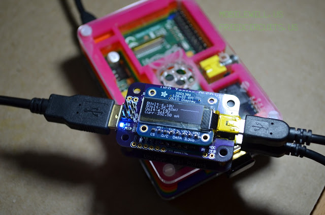
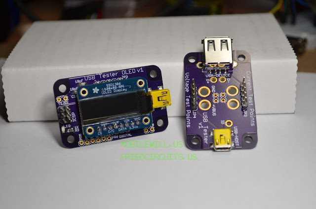
https://tindie.com/shops/FriedCircuits/usb-tester/]. Instead of having to connect your Digital Multi-Meter to the USB Tester you can attach this backpack and get the readout directly on the display. The backpack consists of two PCBs: the first PCB has the microcontroller with sensing circuits and the second contains the OLED display and driver. The OLED display is made by
Adafruit Industries and mates directly to the USB Tester OLED Backpack. The left side of OLED display will show the instantaneous bus voltage, shunt voltage drop, device voltage, and current usage. The right side will display a short term graph of the last minute or so of current usage.
Note: This listing is for the OLED display and backpack. If you don’t own the USB Tester you can buy one here: USBTester. If the fundraiser is successful we plan on selling a kit that will include everything you need: USB Tester, OLED Backpack and the OLED display. We will also create a separate listing for the OLED backpack by itself, in case you already own an Adafruit OLED or just want to use the data logging features integrated into the OLED backpack.
Features:
OLED Backpack:
• Atmega 32u4 (All unused pins are broken out)
• INA219B Current IC from TI
• INA219B can measure up to 3.6Amps in its current configuration. (Adjustable in library code)
• LED Threshold Warning indicator (configurable via desktop application)
• Can be powered from the same source as the measuring device or from a separate USB port
o Doesn’t affect measurements
• Header connection to OLED display
• Arduino Leonardo bootloader for easy hacking
• Source code will be available for download
Adafruit OLED Display:
• 128×32 pixel monochrome OLED Display
• SPI Interface to Microcontroller
• Daylight readable
• Low power with OLED technology
• Able to display graphics and characters
Includes:
• 1x Backpack addon with microcontroller
• 1x SPI OLED Display from Adafruit Industries (includes males headers)
• 2x Female headers for backpack
One of the features added during development of revision 2 was an LED to indicate the proximity to the mA set point. The closer the current draw gets to the set point, the faster the blink rate of the LED. Once the current draw reaches the set point, the LED will stop blinking and stay lit. You can change the behavior by modifying the source code available at the source link to the right.
The OLED backpack can also be connected to a desktop running WindowsOSX(Needs testing)Linux. This connection will let you set the set point, view and record the current, voltage, and wattage via a free Java application download. The source code is included with the Java application so you may modify it to meet your needs.
All of the pins that aren’t being used have been broken out for use in your own projects. One example might be to use the extra pins as triggers. You could set a pin high if the current reaches a certain limit.
The original design called for a switch to select between external / PC power and shared power for the USB Tester backpack. This turned out to be unnecessary since it doesn’t affect the current measurement the way the power is routed. If you do power the test circuit and the backpack / OLED display from the same source it will reduce the maximum power you can draw by about 40mA.
Instead I may include a solder jumper if you ever needed to separate the power sources. I also may include a button that could be used for controlling data logging. Let me know if you would like to see these or any features in the production version.
Note: The current sensor is not limited to 500mA so you could use the backpack to measure other higher current draw devices such as a phone charging or Raspberry Pi Model B. The sensor can measure up to 3.6Amps or less with higher resolution. This is all based on configuration setup in the library. You can view the datasheet for the current IC here: [http://www.ti.com/lit/ds/symlink/ina219.pdf]


Comments 1
Yay, you went beyond the goal. OLED backpacks for everyone.*
*Everyone meaning those who helped fund.