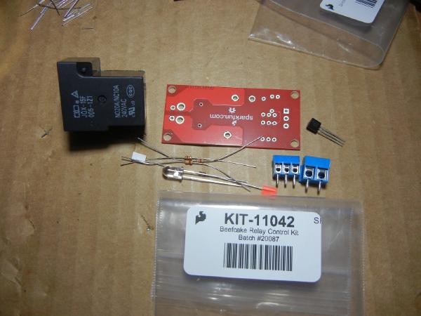
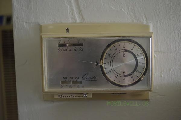
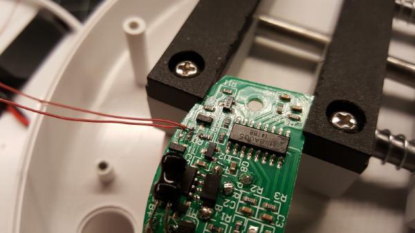
After completing the first version of the smart outlet, I needed a better way to monitor current usage. Using an Hall Effect sensor with an Atmega 328p didn’t work out so well. It was very difficult to get accurate calculations and it tied up the microcontroller from doing other tasks. Proper monitoring should take into account the AC voltage and zero wave crossing.
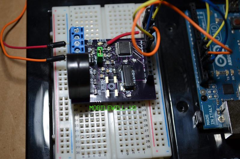
In my research travels I came across this site, http://arduinopower.pbworks.com/w/page/10175892/FrontPage, which mentioned using the ADE7753 from Analog Digital. In theory this IC is great; it does all the hard work for you. You just talk to it over SPI and grab the data. After a lot of research on this IC, I think I was more confused than anything on how to implement it. It requires a lot of external components, mostly passive though. At this point I ended up subconsciously shelving the project.
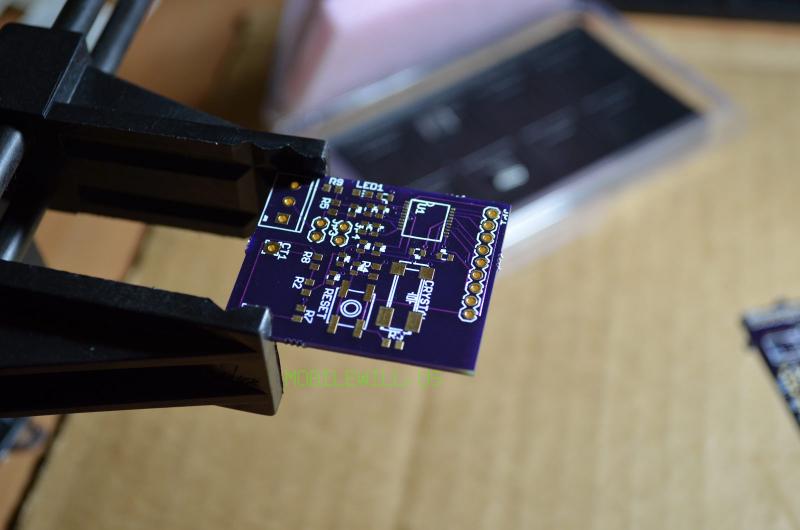
After some time passed, I decided to hit this project head on. Since I have been doing more PCB design I decided to try to lay it out in Eagle and have it printed by OSHPark. (Great way to get small projects printed in the US and in a reasonable amount of time.) After many nights of research and reading different reference designs I came up with a working design.
Two weeks later version one arrived in my mailbox. That night I assembled the PCB and installed it in the smart outlet in place of the Hall Effect sensor. I tried different codes examples from http://pingu98.wordpress.com/2011/07/27/arduinopower-source-code/ and http://www.olimex.cl/product_info.php?cPath=76_78&products_id=797&language=en. The second is pretty close to what I am designing but I want it to be all inclusive. Just hook up AC and DC along with SPI and you are good to go.
For the most part I was able to talk to the ADE7753 and get some data. If the values were right, I wasn’t sure, but at least I had something working. Now off to update the board and print version two. In this version I moved the AC connections to the other side, removed the jumpers and reset button footprint. This gave me more room for spacing parts out and room for proper labeling, which the first version didn’t have.
Another two weeks go by but by this time things didn’t go so well. Soldered it up, wired it to the smart outlet and flicked the switch…. then poof! Magic blue smoke. Since I am working with Mains, it made me quickly jump and freak out. Time to check the damage. At first I thought it was just the resistor on the AC connection for the divider. Upon closer inspection pretty much everything on the board was fried. My oscilloscope showed the crystal acting really strangely. So what does that mean for the Arduino UNO I was using to test? Oops! It’s a goner. The 328p just get hot when running. I wasn’t happy. Then I realized that it was powered from my USB port. Oh no! I hope my computer is okay, I thought. To start, the USB port wouldn’t recognize a device but luckily the USB protection works and clears up the port after a power off reset. Phew! That was close. Now to figure out what happened.
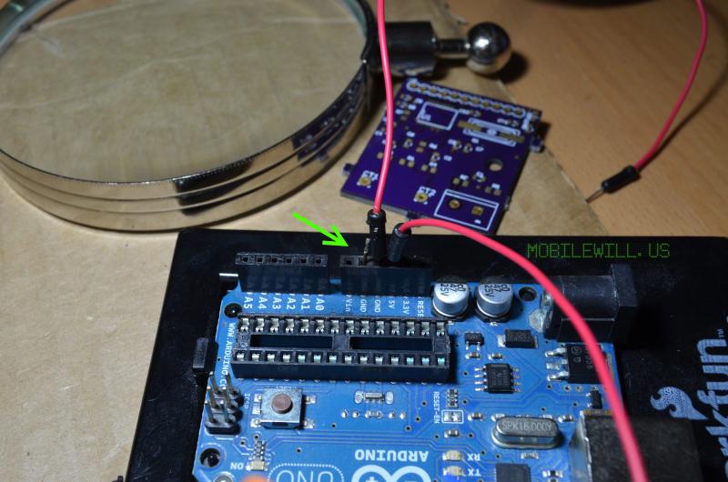
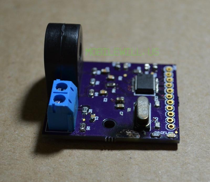
To this day I still don’t understand why it blew up in my face. I had tried it again before I realized most of it was bad by replacing the resistor and just hooking up AC no digital and it melted one of my test leads, so I had molten metal on my desk. Scary stuff. I decided to set it aside for awhile, Mains is not something to play with. This was about November of last year. As write this I think it’s time to get back to it. I know the first thing I need is isolation on the AC input and then condition it before it goes to the input of the ADE7753. I hope this year I can complete this project as I think many people can benefit from it. Once it’s working and tested safely, I plan to sell it on tindie.com. After which I can continue the smart outlet into a final product. I’d like to make it smaller and affordable enough to place one on every outlet in one’s house.
If anyone has experience with this IC please contact me. I would like to see if someone can review the two designs to see what went wrong. Minus not having isolation, I am curious why the first one works. Only thing I can think of is the AC was too close to the ground plane since the first version didn’t have a ground plane.
Update: Here is the design files: https://github.com/FriedCircuits/ADE7753