Last year while visiting a friend for the Portland Mini Maker Fair I became the owner of an IKEA STÖTTA, a battery powered, motion activated, LED lamp. I knew it was ripe for hacking. After arriving home, it sat on my desk waiting to be disassembled to reveal its secrets. I figured the only way to get it off my desk was to get around to tearing it apart and seeing what I could do with it. Over the weekend I spent more time trying to decide which direction to take since there are plenty of features I could add. At least I can get something going now and add to it later. Who ever said a project had to be completed?
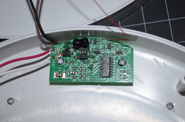 |
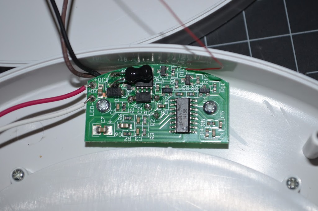
| IKEA LED Light PCB Close Up |
The lamp consists of a small PCB which contains the following main parts;
- HS8A005 (BISS0001 Motion Detection IC)
- PIR Sensor
- LED Driver (Inductor and IC, powered by battery VCC and outputs 3V)
- 3.3V Regulator
- Voltage Detector (Disables trigger on low battery)
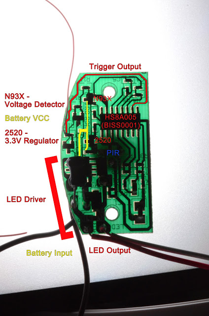 |
| IKEA Light PCB Labeled |
My primary objective is to tap the PIR sensor so that an attached microcontroller can report back to openHAB when there is motion and trigger some other action. After reverse engineering the layout of the circuit, I figured the best way to detect motion from the PIR sensor is pin 2 of the HS8A005 which is the trigger output. Using my EEVBlog multimeter I verified that when this pin is at logic level high (3.3V) there is motion and low (0V) when the timer expires and motion hasn’t restarted the timer. This signal can be fed into an input of your favorite microcontroller.
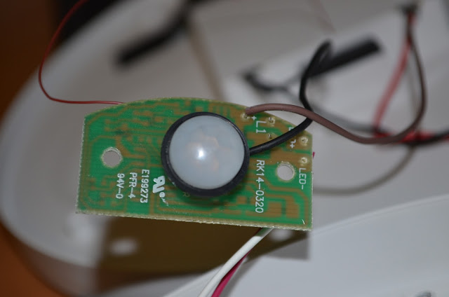 |
| IKEA Light PIR with Lens |
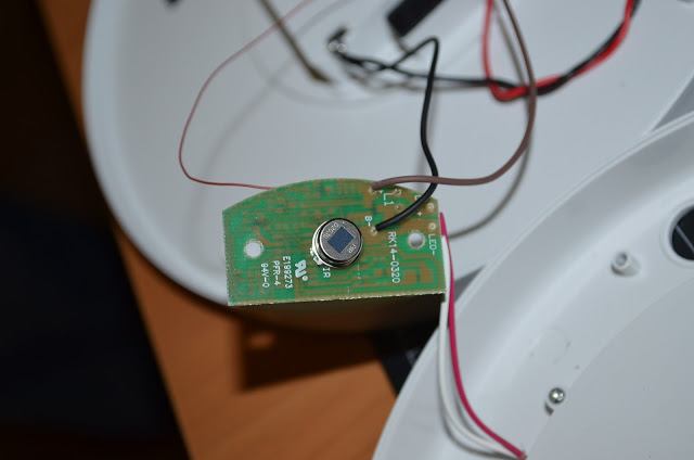 |
| IKEA Light PIR without Lens |
This is where I couldn’t decide what direction to take. Either way I wanted to add a Lithium battery to avoid having to buy and waste AA batteries, that only last a month according to the product listing. I’d rather just charge it once in awhile. The voltage detector runs from the battery voltage and it won’t trigger if the voltage gets too low, i.e. battery is dying. But that means the lithium battery needs to be boasted. I believe the LED driver also uses the higher voltage to boost current when converting to 3V for the LED output, so bypassing the voltage detector probably won’t help. Which also means the LEDs are in parallel.
Using my items on hand I have two microcontroller options I can use. With more time, and I may still do this, I could just design an OSHPark PCB for this project. Which would make it nice and tidy and easier for others to replicate. Hmm…
Option 1:
Use the original blue ESP-01 or a nodeMCU (which I’d rather not use just for a simple project). The ESP-01 would be a good fit of which I have two that I’m not using. This way I can publish directly to the MQTT broker and do over the air firmware upgrades, except for the fact that this version only has 512K of flash. You need 2x time sketch size which the black version of the ESP-01 would have in this case, 1MB.
The other issue with this option is no onboard regulator and limited GPIO but the nodeMCU solves all three. Finally, there is the problem of power usage, which needs just under 200mA when transmitting. I do have an ESP-01 programmer which has the 3.3V regulator but the GPIOs are pulled up to boot from flash and such so I can’t use the inputs after booting.
I did find this awesome schematic just for PIR detection. Given more time and parts I could use this option.
Option 2:
Use a Jeenode (Tiny328) left over from this project: Living Room Node Ugrade. This provides a low powered microcontroller of which I can use existing code. The only thing about that is that I am trying to get away from the RFM12B radios so that I don’t have to have a receiver and python Jeenode gateway that need to be updated to be more reliable. Going direct to the MQTT broker would avoid this. Plus, it is not setup for sending commands only receiving sensor data.
Other options:
For the first version and proof of concept option 2 will work with the Tiny328 and RFM12B radio for now. Now that I think about it, I have some RFM69 radios to play with and this would make a good project for that. I guess that makes a third option. (While writing this and digging out my RFM69 stuff I found a small esp8266 module from Blkbox Tech, but now they seemed to be called Blk box me, that has an on-board regulator and the extra GPIOs broken out, so yet another option. Yeah, I really need to inventory my stuff.)
The first build attempt:
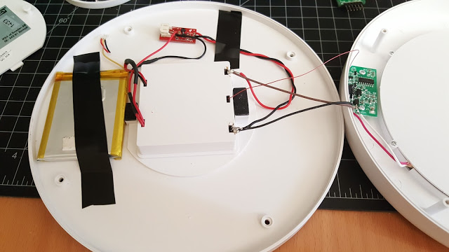 |
| IKEA Light with LiPo and Booster |
To use the lithium battery I will need to boost the voltage. Fortunately I remembered I have two LiPo boosters from Sparkfun.com. This will boost the nominal 3.2V from the battery to 5V. There is plenty of room inside around the battery compartment to tuck in all of the electronics. I decided to only have the battery and booster inside and bring out the charging leads and trigger line to the battery compartment to house the rest of the electronics for easy access for programming and charging.
I soldered a thin wire to the resistor that is connected to pin 2, which is easier than soldering directly to pin 2 on the motion detector IC. As I was finishing up I realized that I would be soldering the live battery wire with a earth grounded soldering iron. For good measure I added a small switch, which turns out to be a nice added feature it didn’t have!
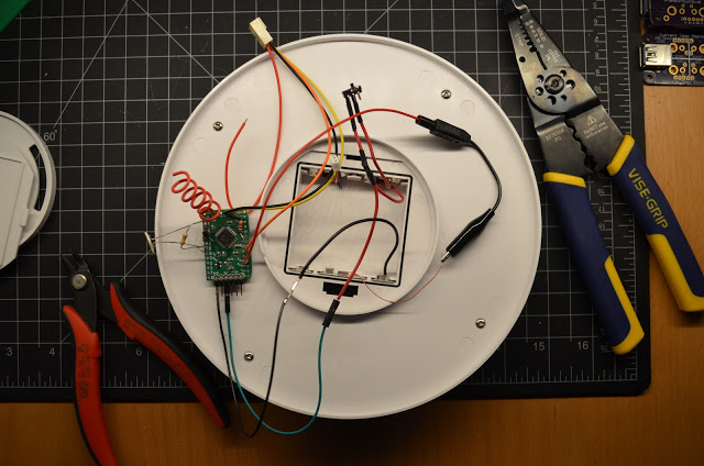 |
| Testing Light with Tiny328 |
Once everything is tidied up, I can close it up and no one is the wiser. It functions as originally intended except it is reporting back when there is motion! Pretty nice. I imagine it being used in a spy movie, LOL.
 |
| Abracadabra! IKEA Lamp in Action |
Future Features:
The Tiny328 still has the LDR and socket for the DHT from the last project. I think I will leave them attached for a future revision of this project. It can be a portable light with environmental data reporting along motion detection. The more I thought about the options, I was thinking I could intercept the trigger output and not only turn the the light on motion but only when the light conditions is low enough or on remote command. I could have the light level adjustable on the fly too. So many possibilities for a simple cheap IKEA lamp. I still would like to figure out a good way to use the esp8266 instead. There are some sleep functions and if I use the nodeMCU, I would have plenty of GPIO, except for the extras sucking up power. Might be time to design a board just for this project. Who knows maybe others would benefit from this. The IKEA lamp mod board! Hmm…

Comments 4
Hi MOBILEWILL
Is is possible to bypass the motionsensor, to keep the lamp turned on whenever the batteries are in.
I would like to hack them for a product display.
Best regards
Mikkel
Author
Hmm, I don’t see why you couldn’t. Maybe jump a wire so it thinks there is motion all the time. It’s been awhile since I messed with this. The battery life with the radio and all that was so short it wasn’t really good in practice. Shouldn’t be too hard to modify it just for staying on.
Do you know a way to increase the ‘on’ time from 30s to f.ex 5 mins?
Easy enough. Have a look at the datasheet provided. The ON time (called Tx in the datasheet) is determined by the value of R10 and C6 in the datasheet schematic or R4 and C4 (?) on the actual PCB, respectively. For 5 minutes ON time (= 300s), simply increase the resistore value by a factor of 10.